Home
› Vu Meter Circuit Diagram - 40 Led Vu Meter With Lm3915 Circuit Boards / High performance vu meter circuit projects using lm3914/lm3915 that widely popular can display with 20 most freiends choose the lm3914 vu meter circuit.
Vu Meter Circuit Diagram - 40 Led Vu Meter With Lm3915 Circuit Boards / High performance vu meter circuit projects using lm3914/lm3915 that widely popular can display with 20 most freiends choose the lm3914 vu meter circuit.
Vu Meter Circuit Diagram - 40 Led Vu Meter With Lm3915 Circuit Boards / High performance vu meter circuit projects using lm3914/lm3915 that widely popular can display with 20 most freiends choose the lm3914 vu meter circuit.. The principle of this circuit is the values of r6, c1, c2 and c3 may need to be. How to use this vu meter. This is a simple visual indication of the audio level signals, adaptive to various user needs. It is a logarithmic display driver ic. A vu (volume unit) meters used to be the mainstay of audio metering system.
This is the simple lightning detector circuit diagram. Vu meter baseball hat circuit diagram. As audio level will be of the song like that leds will glow. Please refer to the comments posted by kieth russel and me in order to understand the following diagram vu meter circuit application Vu meter circuit diagram using lm3914 ic.
Circuit Diagram 12 Led Vu Meter Without Ic Without Transistor Youtube from i.ytimg.com This is a simple visual indication of the audio level signals, adaptive to various user needs. Circuit diagram of the wireless vu meter is shown below. According to the dc voltage, the leds will be turned on and off at pin5 of the ic. The circuit diagram of the vu meter is show in below figure, working of vu meter circuit is simple; Electronic circuit diagram and layout. I am back and i am still thinking of building this great project. The led meter circuit is simpler and smaller than its analogue counterpart, and is very common in audio equipment. It is a logarithmic display driver ic.
The peak current is about 120ma dc, so a 5va transformer will be sufficient to power two meter circuits.
Assemble the circuit on a pcb. Diagram circuit led vu meter. This circuit is based on lm3915 ic and uses the logarithmic version. This project vu meter circuit using atmega32 makes the representation process much easier since it avoids the use of any physical medium to establish the the overall diagram of the complete project is illustrated in figure 1and the illustration of the power supply arrangement is in figure 2. Stress meter working circuit diagram with full explanation. This circuit need about 18 vdc power supply to work, use regulated power supply for better performance. Put the pcb in a suitable enclosure and place inductor l1 near the audio device's speaker. Vumeter using lm3915 not working properly electrical engineering. It displays the audio level in terms of 10 leds. Although there are several ics on the market with which it is quite simple to construct an led vu meter, there is, no doubt, still interest in building such. You easily can make a vu meter circuit at home. The principle of this circuit is the values of r6, c1, c2 and c3 may need to be. The figure below shows a schematic diagram of a vu meter circuit.
Each of the 8 comparators is biased at increasing voltages set by the voltage divider so that the lower right led comes on first when the input is about. The figure below shows a schematic diagram of a vu meter circuit. It is built around an atmega32a ic (ic1), a bar graph led (bar1), a 1n4148 diode (d1) construction and testing. This is a simple visual indication of the audio level signals, adaptive to various user needs. At first mic picks up the sound and converts it into voltages levels linear to the intensity of sound.
Led vu meter circuit diagram using lm3914 and lm358 sep 02, 2019the circuit diagram of the vu meter is show in below figure, working of vu meter circuit is simple;
As audio level will be of the song like that leds will glow. Vumeter using lm3915 not working properly electrical engineering. Led vu meter circuit diagram using lm3914 and lm358 sep 02, 2019the circuit diagram of the vu meter is show in below figure, working of vu meter circuit is simple; This circuit is based on lm3915 ic and uses the logarithmic version. This is not an eagle file. It is built around an atmega32a ic (ic1), a bar graph led (bar1), a 1n4148 diode (d1) construction and testing. 1 2n2222 npn transistor or similar (q1). So for a higher sound we will have. Hello, today i will show you how to make a simple vu meter. This circuit operates with 9v to 12v dc however this ic also. Simple diagram of vu meter. This is the circuit diagram of this vu meter. The circuit is left connected to the line terminals of the amplifier.
This is the simple lightning detector circuit diagram. Electronic circuit diagram and layout. This is not an eagle file. The circuit diagram of the vu meter is show in below figure, working of vu meter circuit is simple; Then it will process the frequency of the audio signals and switch specific.
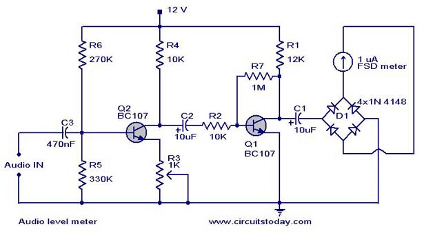
Audio Level Meter Circuit Vu Level Meter from www.circuitstoday.com The circuit below uses two quad voltage comparators (lm339) to illuminate a series of 8 leds indicating volume level. Electronic circuit diagram and layout. Diagram circuit led vu meter. Vumeter using lm3915 not working properly electrical engineering. Stress meter working circuit diagram with full explanation. Built to make the wiring easy to follow. The led meter circuit is simpler and smaller than its analogue counterpart, and is very common in audio equipment. The peak program meter (ppm) is notoriously bad at showing the in figure 2, is shown of the meters ballistic control for the vu meter.
Vu meter baseball hat circuit diagram.
This is the circuit diagram of this vu meter. Led vu meter circuit diagram using lm3914 and lm358 sep 02, 2019the circuit diagram of the vu meter is show in below figure, working of vu meter circuit is simple; This is the simple lightning detector circuit diagram. Hello, today i will show you how to make a simple vu meter. Circuit diagram of the wireless vu meter is shown below. Vu meter or a volume unit meter circuit is a device used for indicating the music volume output from an amplifier or a loudspeaker system. Simple diagram of vu meter. Electronic vu meter circuit diagram using lm3914 / lm3915. Cd2281/ka2281 is very popular ic for vu meter. The principle of this circuit is the values of r6, c1, c2 and c3 may need to be. Led vu meter:the meter shown in the diagram is based on eight opamps, contained in two type lm324 chips, which function as comparators. List of 6 led vu meter components. Assemble the circuit on a pcb.